00 · Hardware
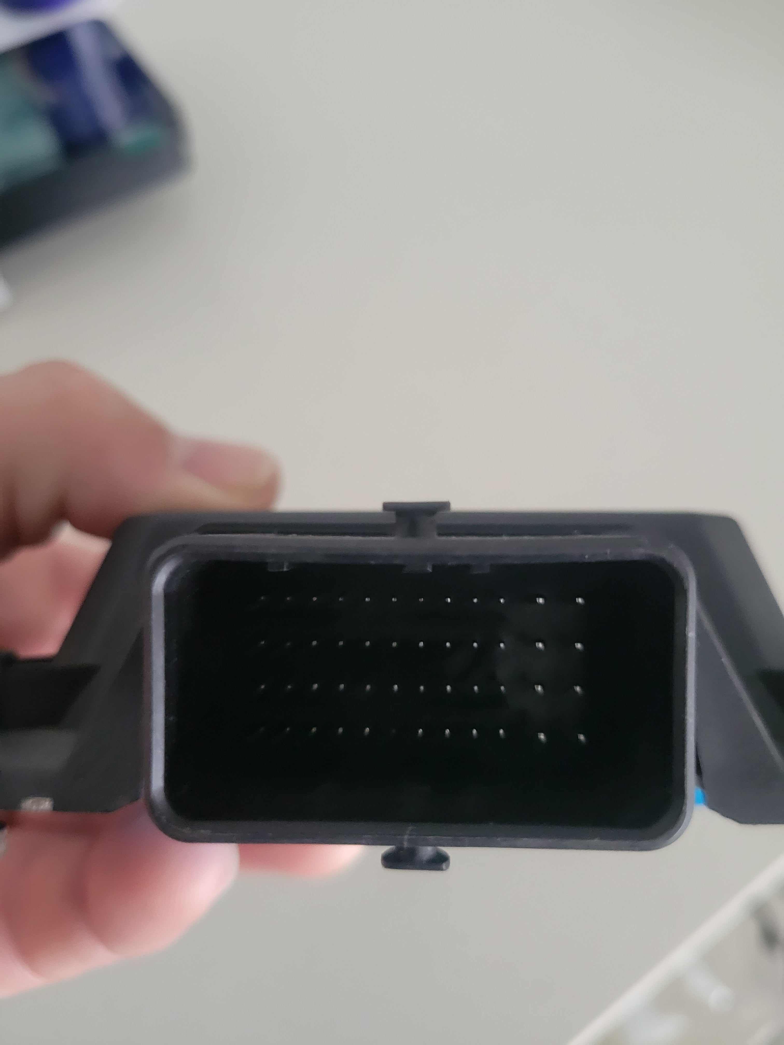
48-pin map 48-way Molex, columns A–M (I skipped), rows 1–4. Looking into the ECU, polarising key at the top. A1 is top-left (CAN High, pin 48). M4 is bottom-right (12 V, pin 1). Typical functions are examples — assign them in TunerStudio.
Filter pins
Looking into ECU · key at top A1 top left · M4 bottom right
A B C D E F G H J K L M
1 1
2 2
3 3
4 4
A B C D E F G H J K L M
Ignition 1 TunerStudio · 9 - Ignition 1
Typical · Coil 1
5 V logic-level coil trigger. Smart coils / igniter inputs only.
Will not fire a dumb coil. Cylinder assignment is in TunerStudio.
Wire · Coil / igniter signal. Coil +12 V from main relay, coil ground to the head.
V4 housing. Match the key to the top of this map. A is the CAN end.
Pin Molex TunerStudio Type Typical 1 M4 Battery Sense 12v 12 V from main relay output. See also E4 (pin 29). Do not forget L4 (pin 5). 2 M3 — gnd Power GND 3 M2 3 - Lowside 2 ls VVT / idle 4 M1 — etb ETB motor + 5 L4 — 12v 12 V from key. Primary on/off supply. 6 L3 — gnd Power GND 7 L2 7 - Lowside 1 ls VVT / idle 8 L1 — etb ETB motor − 9 K4 9 - Ignition 1 ign Coil 1 10 K3 10 - Ignition 2 ign Coil 2 11 K2 11 - Ignition 3 ign Coil 3 12 K1 12 - Ignition 4 ign Coil 4 · 6-cyl injector-driver channel 1 13 J4 13 - GP Out 6 gp_high Tach / 6-cyl injector-driver 3 / 8-cyl injector-driver A 14 J3 14 - GP Out 5 gp_high Tach / 6-cyl injector-driver 2 / 8-cyl injector-driver B 15 J2 — usb USB white wire 16 J1 — usb USB green wire 17 H4 — agnd Signal GND 18 H3 18 - AN temp 1 at CLT 19 H2 19 - AN volt 4 av Spare 0–5 V 20 H1 20 - AN volt 5 av TPS (cable) or throttle-body TPS 1 (DBW) 21 G4 — agnd Signal GND 22 G3 22 - AN temp 4 or Hall Input or Flex at Oil temp / cam 2 / VSS / flex 23 G2 23 - AN temp 2 at IAT 24 G1 24 - AN temp 3 or Hall Input or Flex at Spare temp / VSS / flex / analog pressure 25 F4 25 - Hall Cam hall Cam (sequential) or wheel speed (batch) 26 F3 26 - AN volt 2 av TPS 2 (DBW) / oil pressure 27 F2 27 - AN volt 1 av MAP 28 F1 28 - AN volt 10, Aux Reuse av Fuel pressure / spare analog 29 E4 Main Relay mr Main relay 30 E3 30 - AN volt 7 av PPS 2 (DBW) / O2 / spare 31 E2 31 - AN volt 3 av PPS 1 (DBW) / O2 / spare 32 E1 32 - AN volt 6, Aux Reuse av Wideband analog / spare 33 D4 33 - GP Out 3 gp_low Spare / boost / stepper 34 D3 34 - GP Out 2 gp_low Fan relay 35 D2 35 - GP Out 1 gp_low Fuel pump relay 36 D1 36 - AN volt 8, Aux Reuse av Spare analog 37 C4 37 - Injector 1 inj Injector 1 (4-cyl sequential) 38 C3 38 - Injector 2 inj Injector 2 (4-cyl sequential) 39 C2 — 5v MAP sensor supply 40 C1 40 - AN volt 9, Aux Reuse av Spare analog 41 B4 41 - Injector 3 inj Injector 3 (4-cyl sequential) 42 B3 42 - Injector 4 inj Injector 4 (4-cyl sequential) 43 B2 43 - GP Out 4 gp_low Spare / boost / second pump relay 44 B1 — 5v TPS sensor supply 45 A4 45 - VR/Hall Crank vr Crank VR+ / Hall 46 A3 — vr Crank VR− (do not connect if Hall) 47 A2 — can CAN bus Low 48 A1 — can CAN bus High