Core EFI · Technical manual
V4
48-way Molex pin map, power latch, and assignable 4 / 6 / 8-cylinder examples. Hardware, wiring, software, first start.
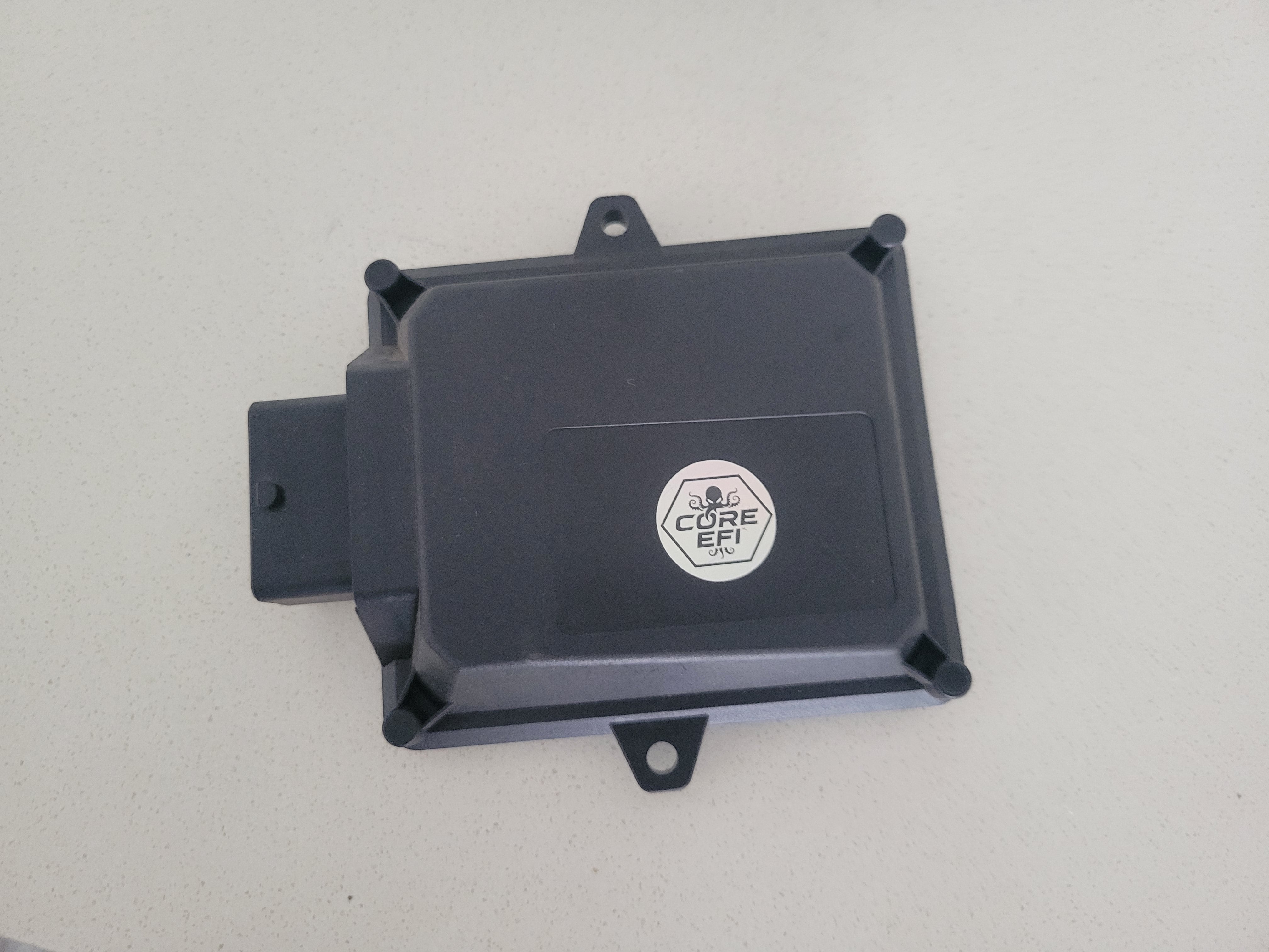
I/O
What is on the connector
| Function | Count | Molex |
|---|---|---|
| Injector (high-Z) | 4 | C4 C3 B4 B3 |
| Ignition (5 V logic) | 4 | K4 K3 K2 K1 |
| GP high (push-pull) | 2 | J4 J3 |
| Low-side | 2 | L2 M2 |
| Half-bridge | 4 | D4 D3 D2 B2 |
| ETB H-bridge | 1 | M1 L1 |
| Main relay | 1 | E4 |
| 12 V in | 2 | M4 L4 |
| Power ground | 2 | M3 L3 |
| Sensor ground | 2 | H4 G4 |
| 5 V rail | 2 | C2 B1 |
| Thermistor | 4 | H3 G2 G3 G1 |
| Analog 0–5 V | 10 | H2 H1 F3 F2 F1 E3 E2 E1 D1 C1 |
| VR crank | 1 pair | A4 A3 |
| Hall | 3 | F4 G3 G1 |
| CAN | 1 | A1 A2 |
| USB | 1 | J2 J1 |
Applications
Cylinder examples
Starting points. Assign firing order, injection mode and spare pins in TunerStudio to match the engine.
| Cyl | Fuel | Spark |
|---|---|---|
| 4 | Sequential on Inj 1–4 (C4 C3 B4 B3) | Logic coils Ign 1–4 (K4–K1). Cam on F4 for COP. |
| 6 | 3-channel matched on external driver: Ign 4, GPO 5, GPO 6 (K1 J3 J4) | Wasted spark on Ign 1–3 (K4 K3 K2). Three coils, two cylinders each. |
| 8 | 2-channel batch: GPO 6 / 5 (J4 J3) into an external driver | Wasted spark Ign 1–4. Pair cylinders 360° apart. |
Manual
Chapters
- 00Molex map48 cavities, A1–M4. Tap a pin.
- 01Power & relayL4 wakes, E4 latches, M4 feeds.
- 02SensorsCLT, IAT, TPS, MAP, analog.
- 03Crank & camVR pair, Hall, flex, VSS.
- 04Injectors4 seq · 6 three-ch matched · 8 two-channel.
- 05IgnitionLogic coils, 6-cyl wasted spark on Ign 1–3.
- 06Drive-by-wireH-bridge, pedal, ETB.
- 07VVT, pump, fanLow-sides and half-bridges.
- 08CAN & dashA1 / A2, Core EFI protocol.
- 09FirmwareDFU, TunerStudio, pin assign.
- 10First startGarage checklist. Fuel last.
- 11FaultsNo RPM, no fuel, no spark.
Connector
How to read the housing
Molex 48-way, columns A–H then J–M (I is skipped), rows 1–4. Looking into the ECU with the polarising key at the top: A is the left / CAN end, M is the right / power end. Row 1 is the key row. Pin 1 = M4. Pin 48 = A1. TunerStudio still numbers 1–48; the letters are the cavity IDs on the housing.